Bluetooth Controlled PWM RGB LED
Reqiured Components
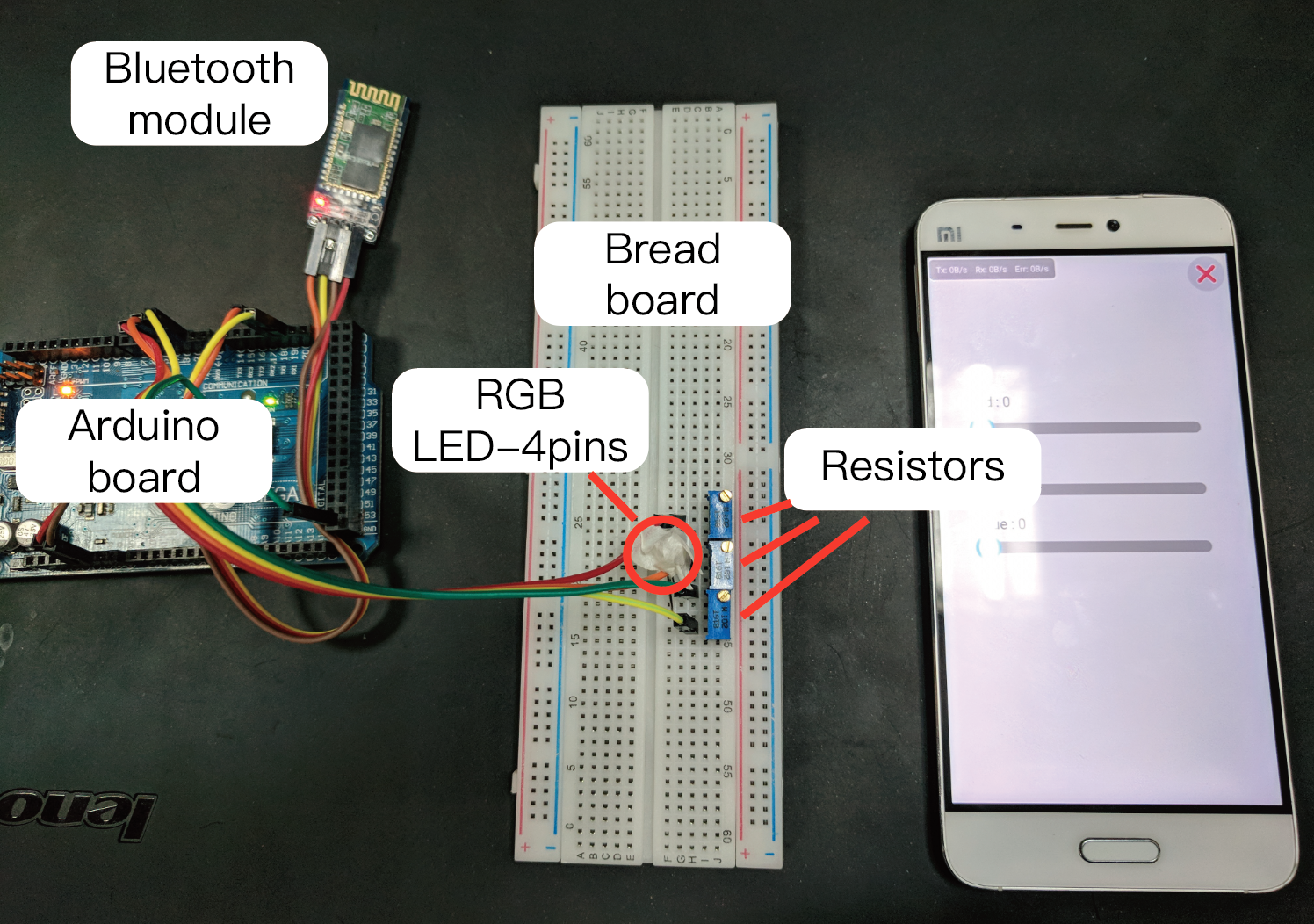
- Bluetooth module HC-05/HC-06
- RGB LED - 4pins
- Arduino board
- Bread board
- Android phone
- 220Ω resistor * 2 or 1kΩ potentiometer * 2
- 150Ω resistor * 1 or 1kΩ potentiometer * 1
Hardware connection
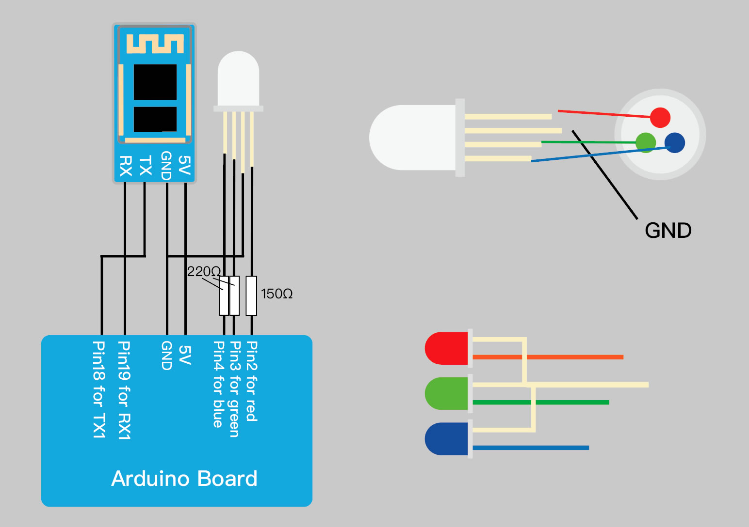
The digital output voltage of Arduino is 5V, and the normal working voltage of our RGBLED is about 2~3V.So we need resistors to limit the current.Since different colors of led have different brightness at the same current, we need to give different resistances.
Arduino code
1.Download code template
2.Define data packet structure
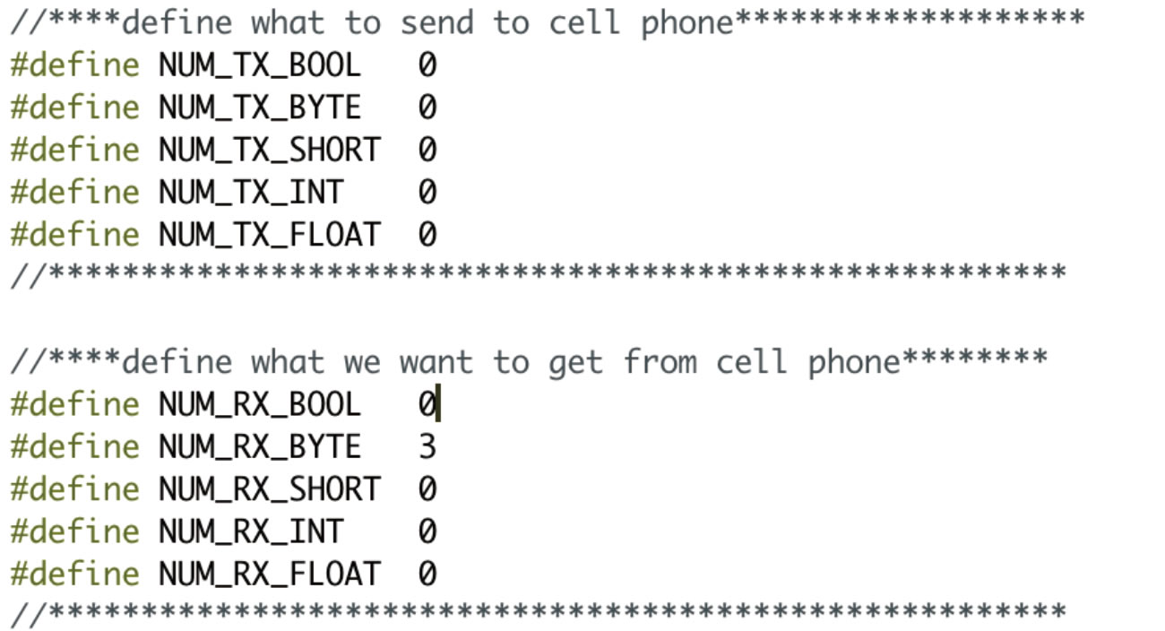
You'll find a few lines of code at the head of the code template that defines the structure of the packet between the microcontroller and the phone.
We have to control 3 leds with pwm, so we define 3 byte variables in the code. Other code is related to the underlying communication, please keep it as it is.
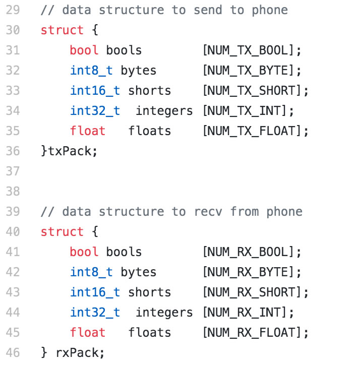
There are already two structure defined in code template as shown above. The txPack and rxPack. You can directly access the variables in the structure by the form like 'var = rxPack.bytes[0]'
3.Code
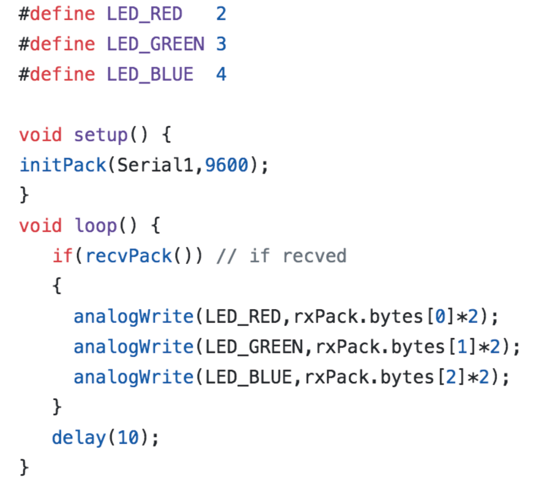
There are only three functions to use to implement a complete data transfer.
- void initPack(Serialx,int baudrate)
Initialize the working conditions of the communication. You need to specify which serial port to use and the baud rate of the serial port. 'Serial' is correct if you connect bluetooth module with pin tx0/rx0. If you use pin tx1/rx1, you should use 'Serial1' as shown in example. - bool recvPack()
Try to receive data from your phone and return true if data is received. You need to call this function at a short interval. - void sendPack()
If you have sensor data to send to your phone, you will need to call sendPack() each time you change the txPack variable.
BTMCU Configration
1.Create a project
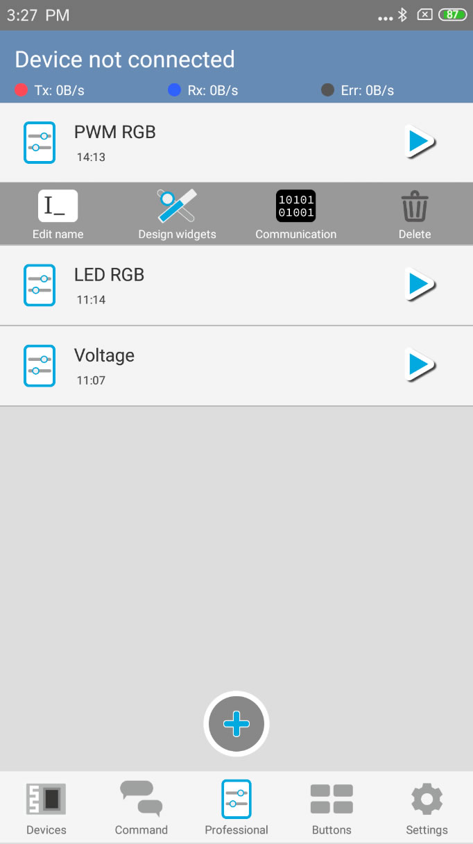
The first step is to create a project.How to create a project?
2.Configure communication parameters
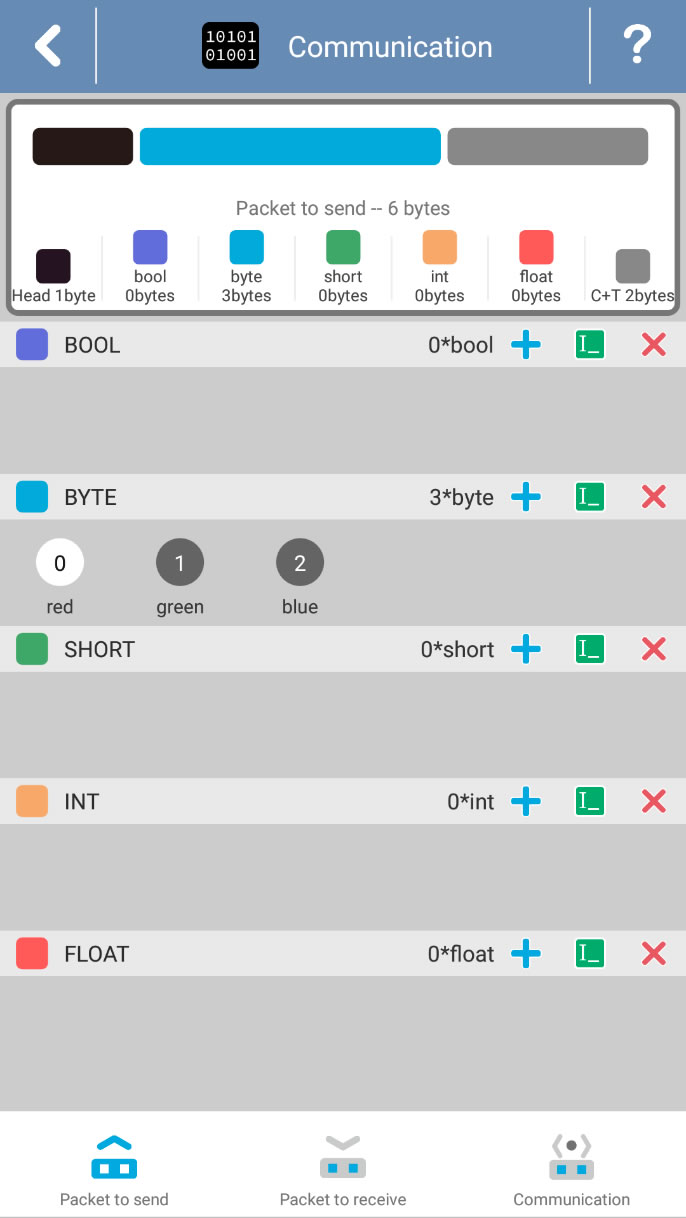
Then you need to define the packet structure in communication page.How to configure?
3.Edit widgets
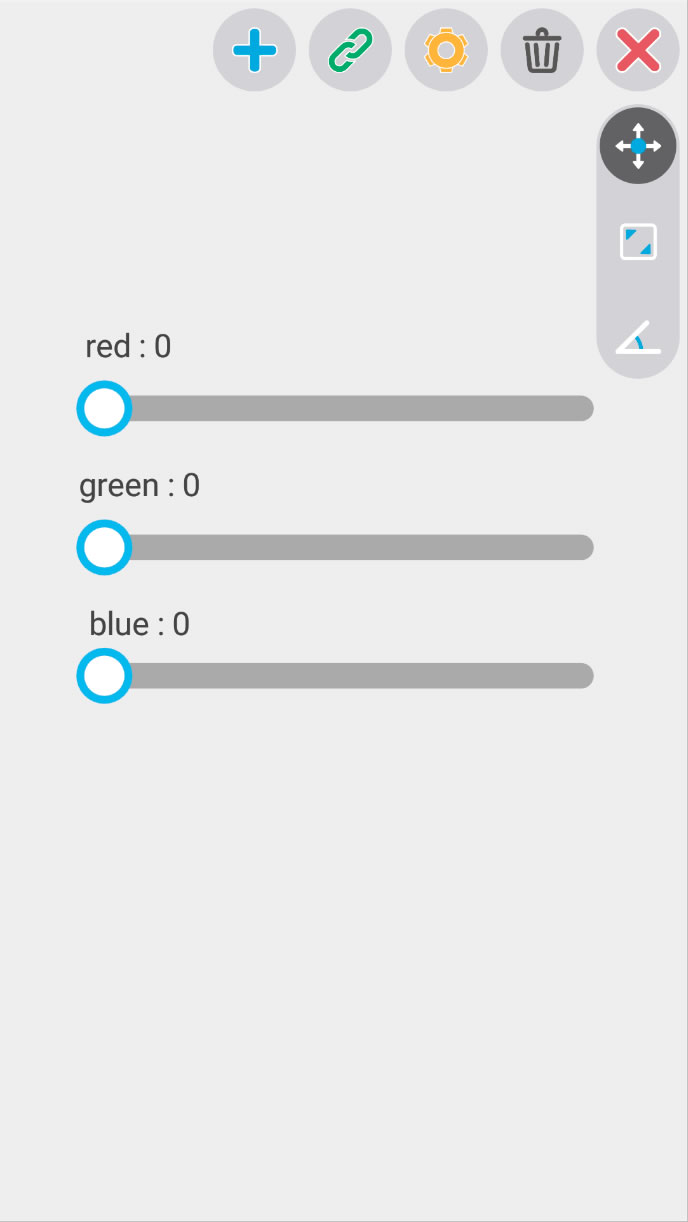
Create three seekbars to control RGB LED. One thing to notice is the range of byte. The range of byte is -128~127 in BTMCU, but we want to get 0~255 in Arduino. The first solution is to narrow the range of seekbar to 0~127 then '*2' in Arduino program. The other solution is to '+128' in Arduino program to get the value in 0-255.
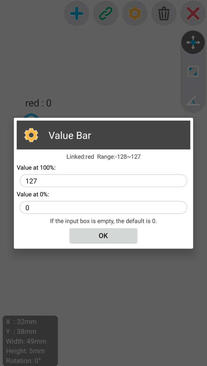
I chose the first way, so I need to modify the value range of the seekbar. How to edit?
4.Scan and connect
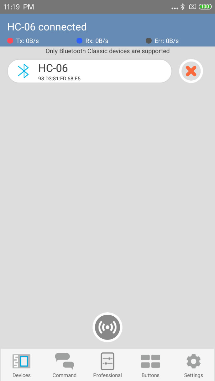
Configuration is finished. Scan and connect the bluetooth device.How to connect?
5.Run project
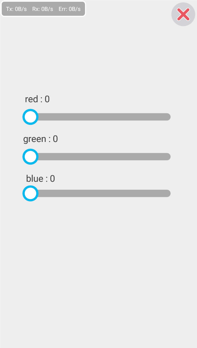
Finally, run the project.How to run?
Hope you can make amazing works.